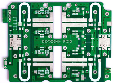
What should We Pay Attention to When Making High-frequency Circuit Boards?
Nowadays, electronic products are developing towards miniaturization, funtionalization, high performance and high reliability. The high-frequency board is high-frequency circuit board, which is one of the most difficult boards, so it must meet the production requirements as much as possible. It has been widely used in various industries such as heat processing, heat treatment, thermal assembly, welding and melting of special materials. It can not only heat the workpiece as a whole, but also heat the workpiece in a targeted manner. It can realize the deep penetration of the workpiece, or it can only heat the surface and the surface layer. It can not only directly heat metal materials, but also indirectly heat non-metal materials. So, induction heating technology will be more and more widely used in various industries. Its various physical characteristics, accuracy and technical parameters require very high, and it is often used in automobile collision avoidance systems, satellite systems, radio systems and other fields.

The new high-frequency circuit board is provided with ribs at the upper and lower opening edges of the hollow slot of the core board, which can block the flow of glue. In this way, when the core board is bonded to the copper clad laminates placed on the upper and lower surfaces, the glue will not enter the hollow groove. That is, the bonding operation can be completed with one processing. Compared with the prior art high-frequency circuit board that needs to be pressed twice to complete, the high-frequency circuit board of the present invention has a simple structure, low cost and easy manufacture.
Solder Mask
1. If you need green oil to make the base, it is not allowed to grind the board before the solder mask, and the red seal is stamped in the MI.
2. If the high-frequency board needs to be printed with green oil on part of base material, and some base materials are not printed with green oil, a “priming film” is required. The base film only retains the green oil on the substrate, and the second normal production is performed after the base baking sheet.
If the high-frequency board substrate needs to be printed with green oil, it should be printed twice to prevent the green oil from blistering on the substrate. Before removing tin, do not grind off the etched board, but air dry.
Drill
1. Special attention: No need to remove glue residue.
2. Grinding board, plated though hole, circuit and normal double-sided production.
3. PTH hole template can use concentrated sulfuric acid as pore sizer. It is best not to use concentrated sulfuric acid.
4. The drilling feed speed should be slow to 180 /S. Use a new drill bit with aluminum sheets on top and bottom. It is best to use a single PNL for drilling. There must be no water in the hole.
SHENZHEN HOYOGO ELECTRONIC TECHNOLOGY CO., LTD. is a manufacturer specializing in the production of high-precision double-sided, multilayer and impedance, blind buried vias, thick copper circuit boards. The products cover various circuit boards such as HDI, thick copper, backboard, rigid-flex combination, embedded capacitors, gold fingers, etc., which can meet the needs of customers for various products.
评论
发表评论